Rule Editor
Rule Assembly Workflow
Rules Emerge from Human Relationships
In the Oughtomation paper, a rule is defined within specific terms. From figure 2 an important conceptual distinction is described.
Figure 2: Six types of normative data which may be communicated.
| NORMATIVE DATA | DECISION | PROPOSITION | PREROGATIVE |
|---|---|---|---|
| MUST, MAY and SHOULD | Empirical Statements | Declarative Statements | Imperative Statements |
| GENERAL CONTEXT | Deduce from evidence that this system of rules is ‘in effect” for this jurisdiction and time. | Describe a system of rules. | Acknowledge a system of rules. |
| PARTICULAR CIRCUMSTANCE | Deduce from evidence that this rule is ‘applicable’ to these facts. | Describe a rule. | Acknowledge a rule. |
From this it is clear that a rule that enters an Oughtomation specification network is a description of a rule based upon "some type of agreement, authority, resolve or preference." To this end an author using RM is tasked with describing an agreement that exists within a complex, dynamic rule system, emerging from living human relationships. These agreements are often described in formal legal documents, but may be documented in other ways such as meeting notes, a transcript of a conversation, a photograph, a note scribbled on a napkin, or any number of other methods.
No matter the form of the document, the core authorship mechanic remains constant. An author, examines a document and describes a rule as normative data using a logic table. It is clear that before a rule exists within an Oughtomation network, it first exist in a form that is embedded within a human readable artifact.
This is further evidenced by the fact that one of the core pieces of metadata in the rule schema (XRS) document is a rule-url field. This field is intended to ensure there is always reference to the rule's originating document. However, this choice also provides an important insight into the mechanics of an authorship process.
When an author decides to describe a complex and animate rule system based on living relationships, they may not know things such as:
- how many
rule.xalgodocuments will be required to fully express this rule - how this description will be best be represented as a logic table
- how many structured natural language sentences will be required
- what data tables will be required for rule evaluation
Dynamic IDE Assembly
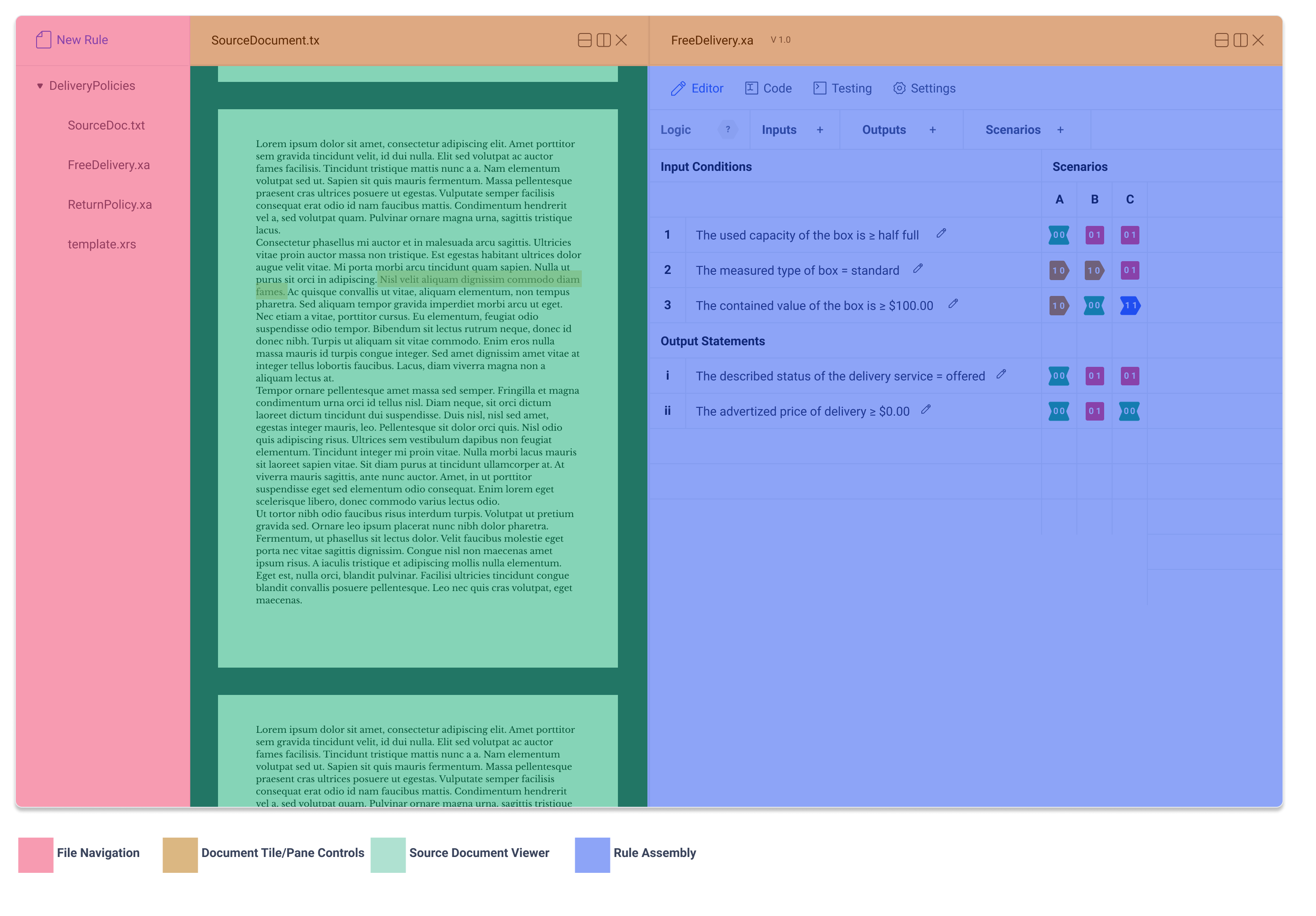
To this end, an authorship process begins with examination of a source document and rule(s) are derived from careful and concerted description efforts. Annotation, isolation of clauses, etc. are all valuable tools that will aid the author in this effort. More important to the core mechanics of XRM Dev, an author must be able to create rules, and edit logic table while examining a source document.
Understanding this dynamic give important clues to the nature of the IDE environment. Crucially, an author must be able to view more than one rule.xalgo document at once. They must be able to use the multi-plane environment to view a single source document while switching between the assembly and testing panels of multiple rule documents.
Coming to this realization makes me think back to a piece of advice Don Kelly has repeatedly given: "RM is a text editor". This comment has taken on further meaning. RM is a text editor, and therefore, it should be able to open a text document. However given the limited dev capacity, this is not the primary objective. The focus of the reference implementation must be on the assembly of logic tables and description of metadata. However recognizing that these element are derived from a document provides important insights about how top level controls such as creating a new document, and opening existing documents are handled.
In summary, it will eventually be useful to conceptualize RM as a specific kind of note taking application. However, the ability to view source documents must not be the priority at this point. Yet even without this feature, conceptualizing the application with this workflow in mind will improve usability. Even if authors open a source document in another application, they will still be able to enjoy the kind of functionality they are looking for in a rule assemble environment, even if they lack the ability to view that document directly in rm application.
This means a file browser to the left will be required. Within this module is a new rule button. This means that each pane need to display the file name and offer pane controls. See Split Pane for more details.
Tabs
The IDE environment is comprised of four tabs:
- Rule Assembly
- Rule Metadata
- Logic Table
- Raw Text
- Testing
- Settings
Layout
Concerted effort went into thinking about where each element sits within the window. Not only must the layout provide intuitive placement of the different elements, it must also do so effectively, even with reduced horizontal dimensions (since the split screen will limit the x dimension of the panel).
| Layout Requirements | -- | -- |
|---|---|---|
| have all the pages accessible via a submenu even when multiple panes are open | have all table controls accessible even when all panes are open | display maximum amount of table information given t once the other two requirements have been fulfilled |
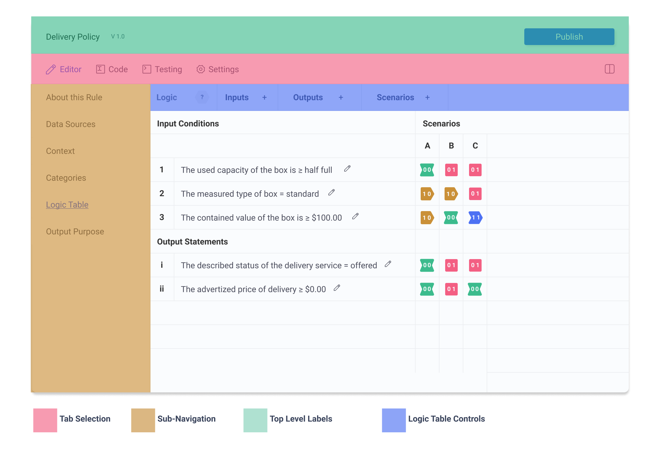
because the application is multipane, it is imperative that controls and sub-navigation are accessible when even when half of the screen is occupied by another pane. This means that the sub-navigation must be located on the left hand side. There are too many tabs for it to be located below the navigation, since when the screen is split, tabs are lost.
Similarly this puts a width constraint on the logic table control panel. Being located on the top means there is clear differentiation between the different submenus. Per application standards, these controls must consist of both an icon and a label, for maximum accessibility. However, this requires that the labels are as concise as possible, so that important control information is not hidden It's width must be as small as possible so that controls are accessible even withe reduced x dimensions.
Multipane
The author may split the screen horizontally to access multiple instances of the IDE interface.
Essential actions
This application must successfully allow the user to accomplish their desired actions, and nothing more. In order to prioritize effective authoring, the required actions must first be defined.
- add and remove columns/rows
- reorder columns/rows
- edit structured natural language sentences
- select logic states
With just these simple actions, a huge amount can be accomplished. By focusing on these very limited actions, I can ensure these key areas are carefully considered and preform to maximum effect.
Bounded Action Areas
Having bounded action areas can greatly reduced the complexity of the control table panel. To this end, the control table is divided into four areas that each contain only one type of important information.
- Control Panel The control panel holds controls for logic state selection, and table/ row manipulation controls
- Table/Row Displays the labels for the table/row
- Sentence Controls This section displays the structured natural language sentences and provides a control to bring up editing modal
- Logic State Displays the logic state of row and column as well as allowing for basic logic state selection.
This is a huge improvement. Previous iterations had controls mixed throughout the different areas. The result was confusing with fewer opportunities for well defined control actions. With controls separated, not only is the layout more straightforward, this process has allowed each control to considered in a more complete manner.
Progressive Disclosure & Contextual Actions
An important tool for managing informational complexity is to hide actions until they can be performed. Brandon Walkin writes further about this.
In practices, this means that all column and row actions are hidden within their sub-menu until selected. Furthermore, these menus can be simplified by relying on column and row selection. By clicking on the row or column label, the entire row/column can be selected, giving the author the option to reorder or delete their selection. Without selection, these options are hidden.
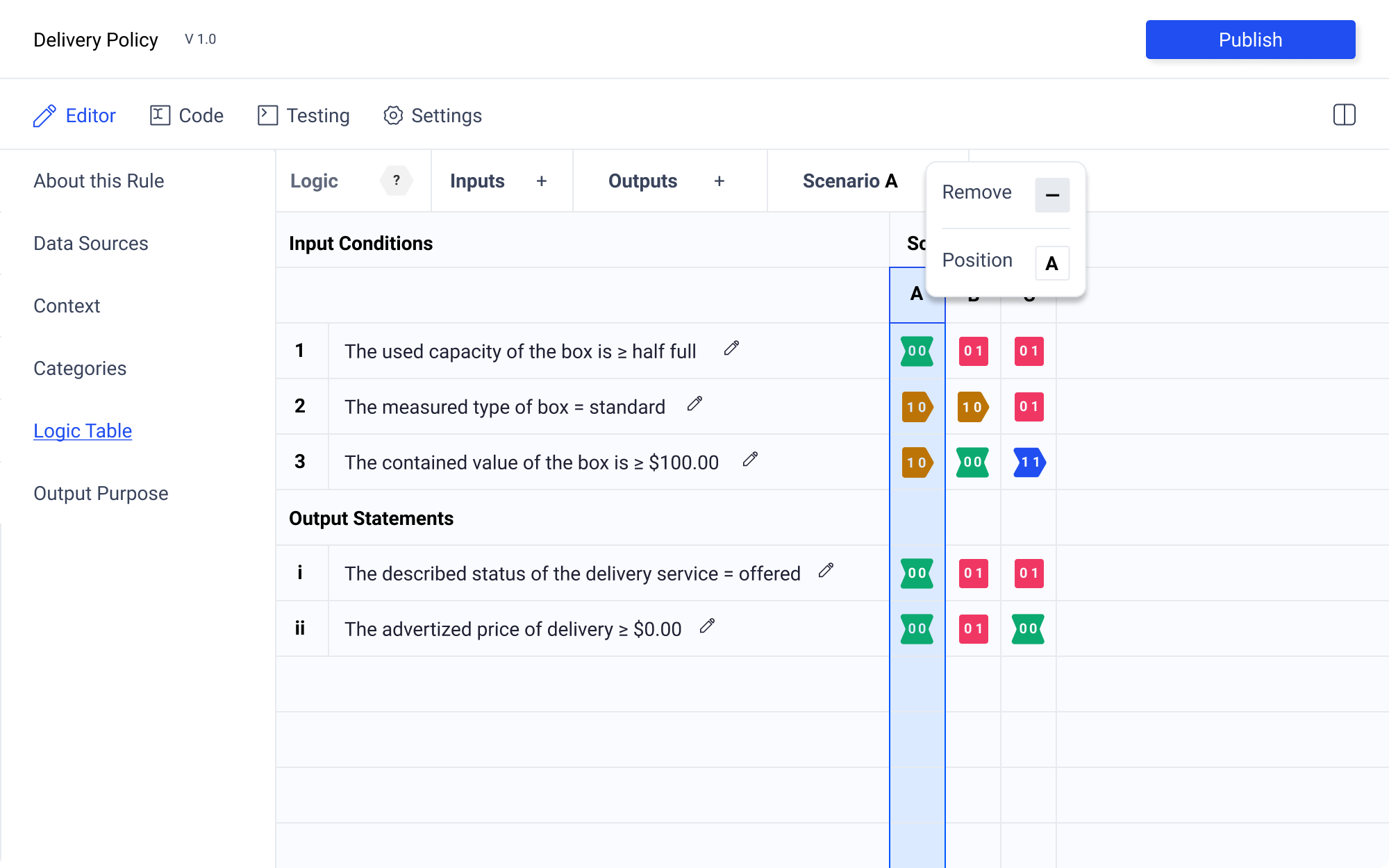
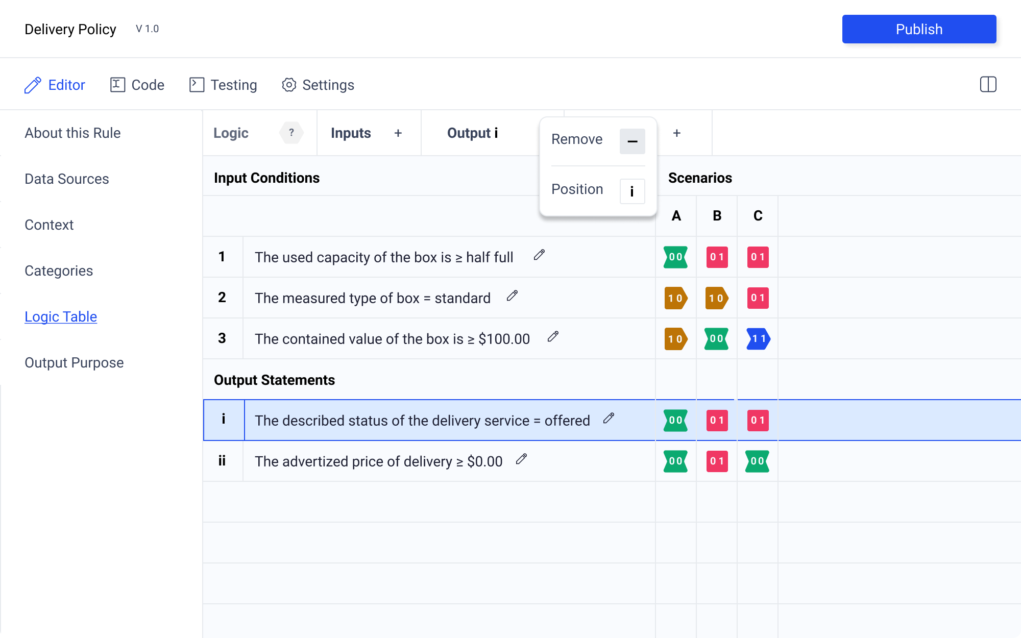
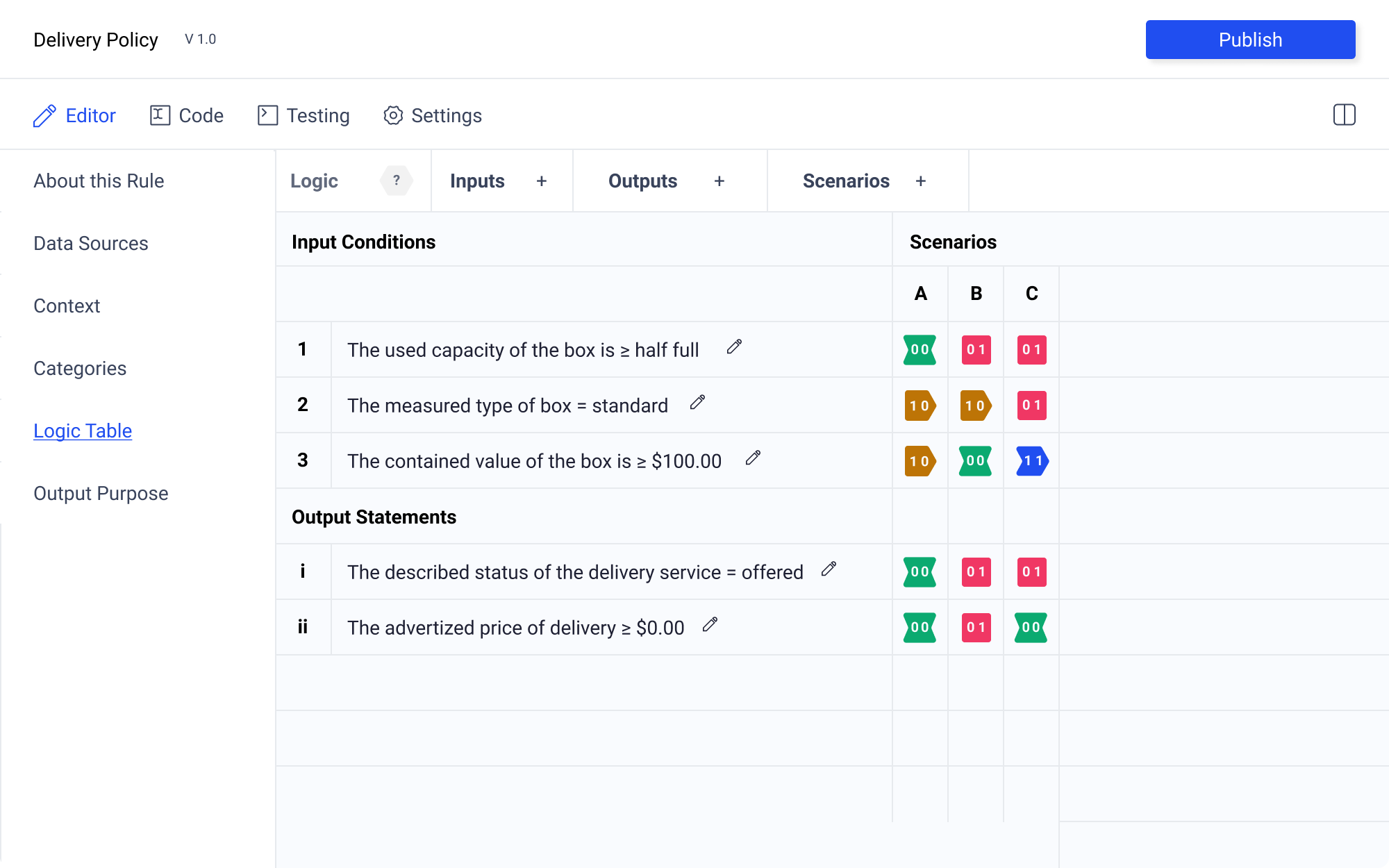
Grid Labels
The rows should be label for easy orientation. However, given the distinct nature of Input Conditions and Output Assertions, the two should be labeled in a way that distinguishes the two. To accomplished this, Input Conditinos are labeled numerically (123...) and Output Assertions are labeled using lowercase roman numerals (i ii iii...). This is important so that the 1 and an uppercase I are not mistaken for the same numeral, making the author think that the two statements need to be connected. The scenario columns are label alphabetically (A B C...) following convention established by existing spreadsheet editors.
Hover and Selection States
A key piece of successful logic state icons is the ability to select. Not only is this a crucial part of the authoring process, but also provides an opportunity to create another layer of of accessibility.
Hover states are a key piece that help indicate functionality, but can also be used to help further aid visually impaired people distinguish between pieces of information.
Change color. Even if the user has trouble seeing color, there is a value change, meaning the outline gets darker. This is noticeable but is not perfect.
Editor Actions
Rows And Columns
Selecting a row or column allows the author to edit this element. Using the numeric or alphabetic label, the author can select the entire row or column. From here they are given the option to delete or reorder. These controls appear in the left hand control panel. At the same time, the row or column label appears in the control panel indicating which row or column is being edited.
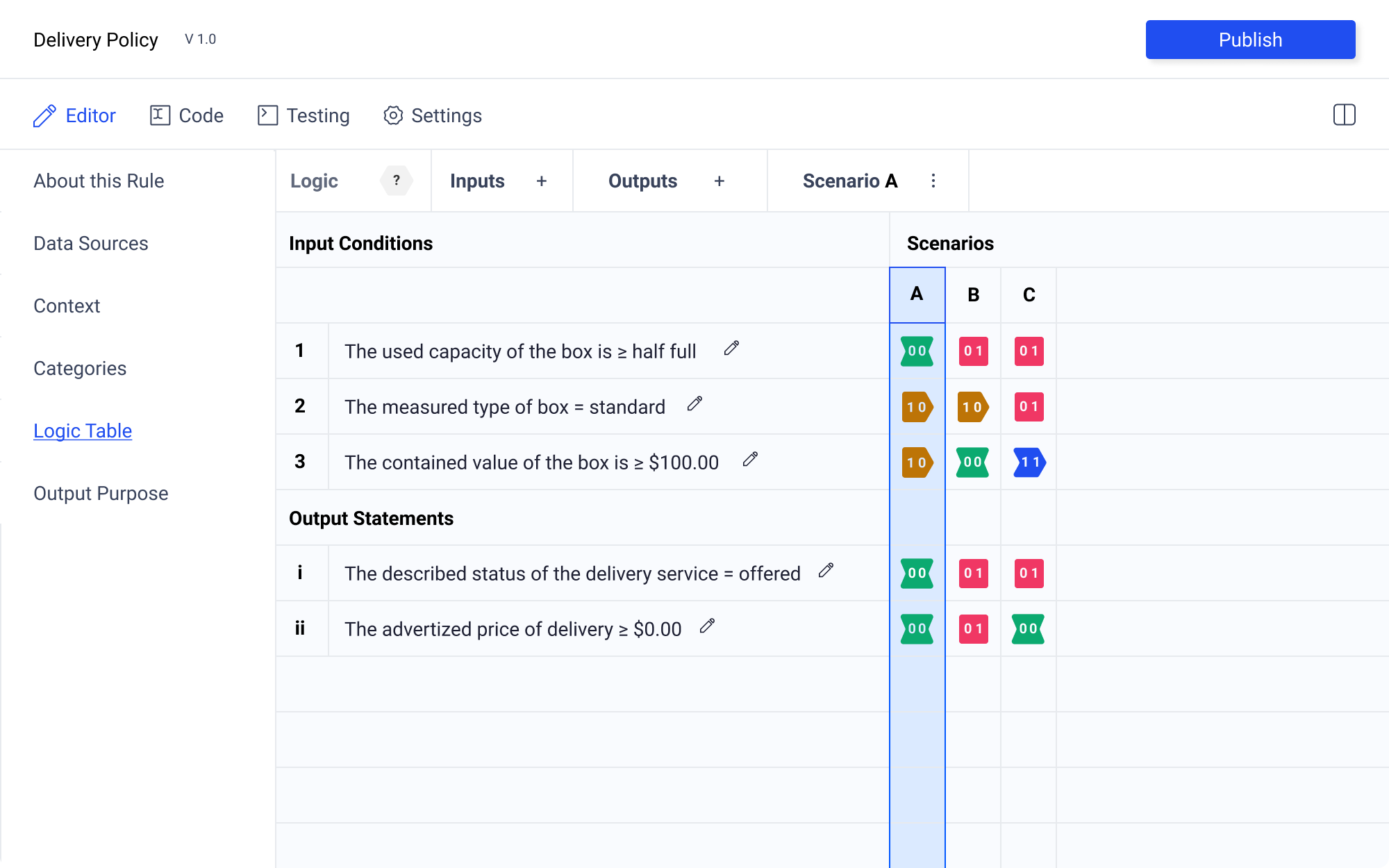
Having the left hand control panel allows for a great deal of flexibility. My preference is to allow the author to reorder rows and columns by dragging and dropping actions. However, this will likely be difficult to execute. If this proves to be the case, the left hand control panel provides plenty of room for additional controls to be added for any element.

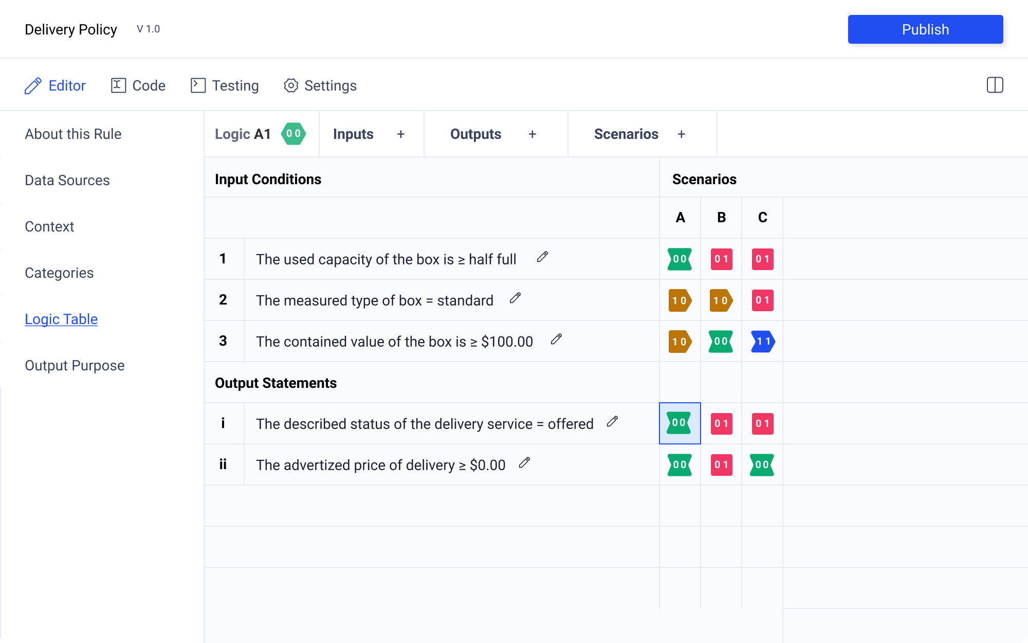
Logic State Selection
Selecting a logic state will enable options in the control panel. The logic state icon will be populated if one has already been selected. Additionally the coordinates will also populate the control panel ensuring clear orientation. The selected logic state will be highlighted with a blue outline and light blue background. Hover state will be just the blue outline.
There are multiple ways to select the desired logic state. The author may click to select the element. Upon selection, they may click again to cycle through the logic states.
Alternatively, the author may select the logic state icon from the control panel the reveal a pallet of logic state icons.
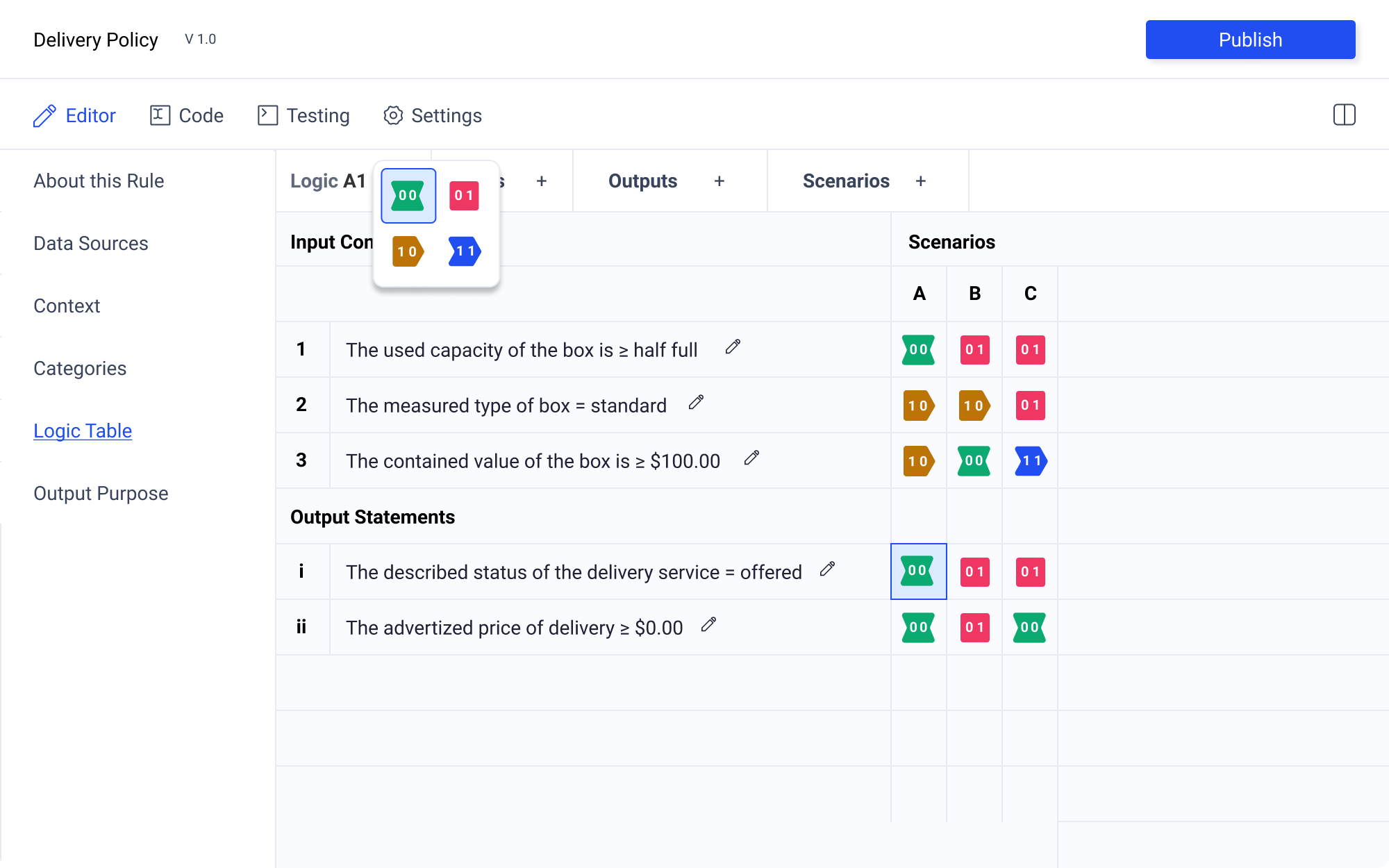
Having the logic state icon pallet separated from the control table is crucial for legibility. Upon testing selection in table, I found that no matter the shape of the modal, or background treatment (even darkening the rest of the table, with only the logic state icon pallet in focus) that there was too much visual information. Having the pallet in the control panel requires more mouse movement, but this trade off is worth it for the much improved clarity.
Sentence Constructor Modal
Sentence Elements
The sentence construction modal is one of the most important elements of the applications. Structured natural language sentences, allow authors to describe rules as normative data. See a full explanation of how this accomplished in the Oughtomation Paper.
A sentence is constructed by the author entering strings into the following fields:
- Determiner
- Subject Noun*
- Past participle*
- Auxiliary Verb
- Object Descriptor*
- object Noun or Verb
The fields marked with asterisks are required. Each field may only appear once. The sequence of the fields must retain controls for reordering
Domain Experts as Authors
When thinking about the creation of a interface, it is important to note that the application is intended to facilitate:
"the management of semantics in the hands of people who have the prerogative, motivation, domain knowledge and socio-cultural familiarity to tailor the expression of each sentence of each rule, who are motivated to make a genuine effort to provide a faithful reproduction of the full normative intent of the original rule with minimal distortion."
This underscore the importance of making the sentence construction accessible to all authors. This is challenging particularly for new users. Although the mechanic eliminates many of the barriers to creating rules transmitted on digital networks, the interface is not obvious to novice users.
Importantly, using labels to describe the inputs is not an ideal solution. Describing different parts of speech utilizes technical terminology in a way that may make even native speakers unsure of what's required. As Joseph Potvin has suggested, labels should be secondary, with an emphasis placed on practical examples. By leading with examples, and allowing authors to discover sentence patterns for themselves is the most feasible way to ensure domain experts themselves have the ability to author rules.
Field Requirements
From the previous two sections, some requirements can be defined. To facilitate the authorship process each field must:
- indicate if a field is required
- allow the author to reorder sentence elements
- present examples
- function within a window with minimal horizontal dimensions
With the constraints a clear picture emerges.
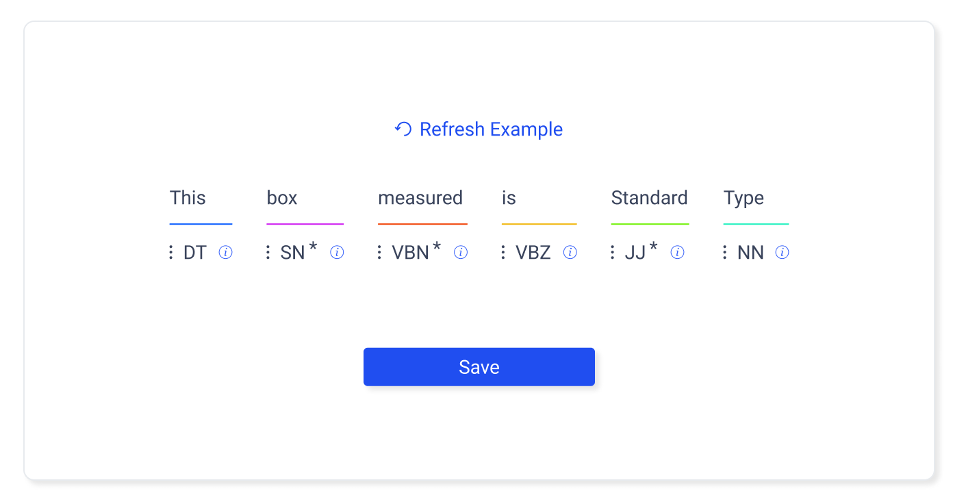
Examples
Examples populate the fields as hints. Crucially the labels are beneath the input, so that the author see the example for being presented with a technical explanation. additionally, there is a refresh button that will allow the author to cycle through examples.
Labels
Given the limited space, and the fact that the labels for the parts of speech are given lower priority than textual examples, the labels are condensed to abbreviations. To give additional distinction, each field has a differently color underline.
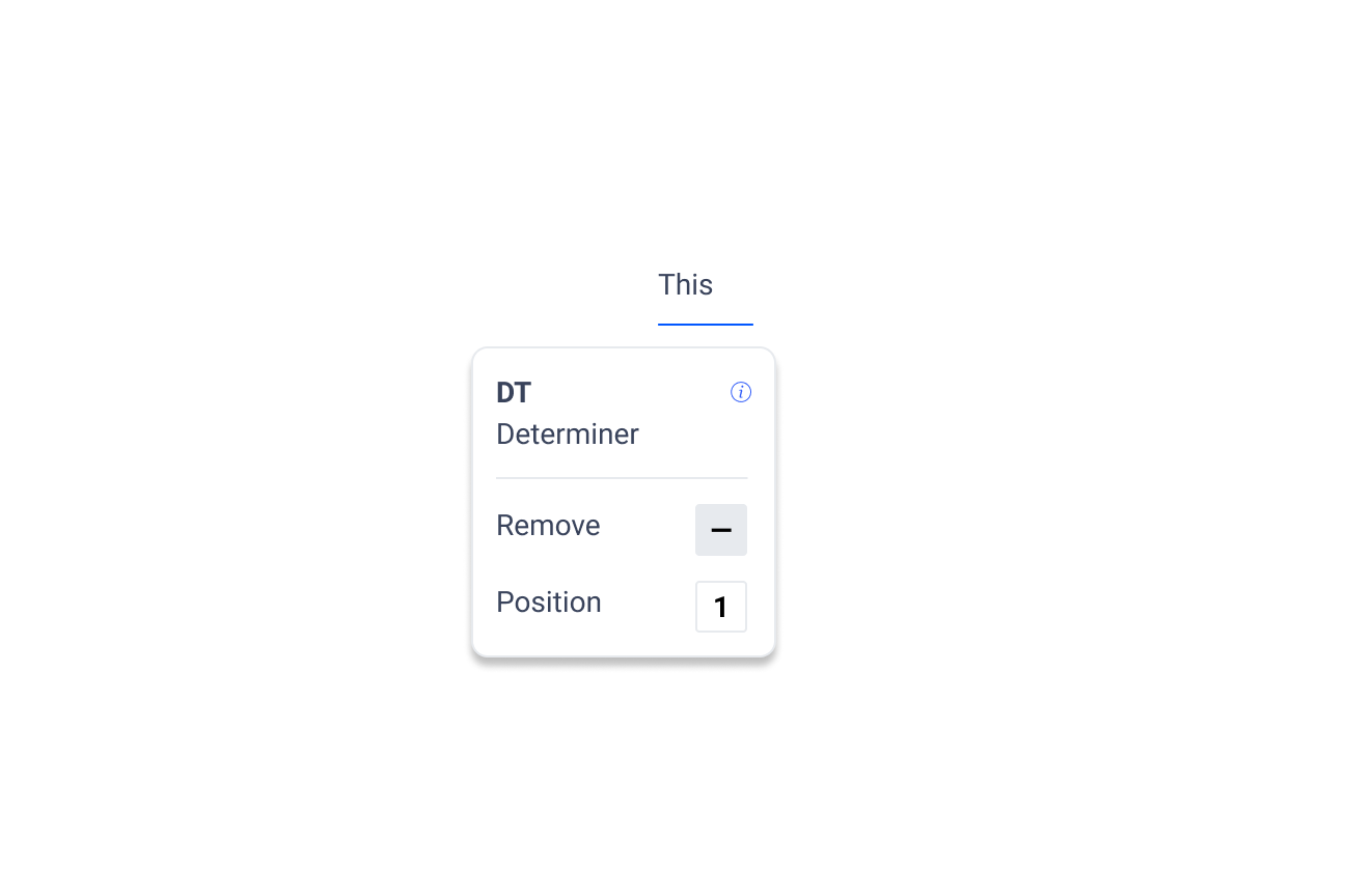
Progressive Disclosure
When the author clicks on the bottom label, full label information is revealed along with control options. Input controls enable reordering and removal of non required fields.
Adding Removed Fields
If a field is removed, a button will appear at the end of the sentence allowing the author to add that field
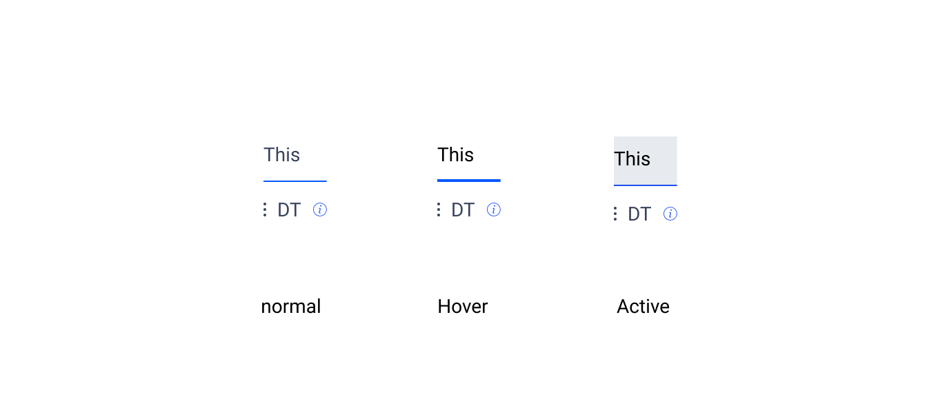
Hover States
Hover states the text is darkened, and the underline is increased to 2 pixels.
Active States
A background is added to the fields along with darker text.
Default Logic State Icons
| Context | User Need | Design Requirements |
|---|---|---|
| A user is authoring rules using the table editor | They need to be able to easily distinguish between the different logic states when selecting, but also be able to see the macro pattern that emerges from the table when complete | Have multiple forms of visual redundancy to make the logic state clear. this means using shape, color, and label in combinationt |
| Correct balance between high contrast for easy logic identification vs having a ui that is not straining/tiring on the eyes is crucial |
The icons indicating the quaternary logic state are one of the most important UI elements. Legibility, and at-a-glance comprehension are crucial for effective rule authoring and review.
The greatest challenges facing an author is the density of information presented on the table editor tab. Fortunately significant research exists in this area. UX Matter states that "The greater the density of information on a page and the greater the distance between highlighted visual elements, the more this type of color-coding improves user performance. Because color is such an effective visual cue, its use can also reduce eye scanning movements and, thus, visual fatigue.
However it is also important to not that color alone is not sufficient. W3 mandates that "Color is not used as the only visual means of conveying information, indicating an action, prompting a response, or distinguishing a visual element."
In order to ensure the maximum accessibility of this information, three layers of redundancy are required. These are label, shape, and color.
Label
The labels for the default logic state icons are defined in Joseph Potvin's forthcoming Oughtomation paper. They are as follows
Labels | -- | -- | -- | -- 00 | 01 | 10 | 11
Color
How do we choose the colors. There are a few important constraints. First the logic being represented is quaternary. That means we need 4 distinct, highly contrasting colors. These means we can make use of a square color wheel constraints. However, this color scheme also needs to be conformant with the brand guidelines. Using the main blue as the square base we get the following scheme.
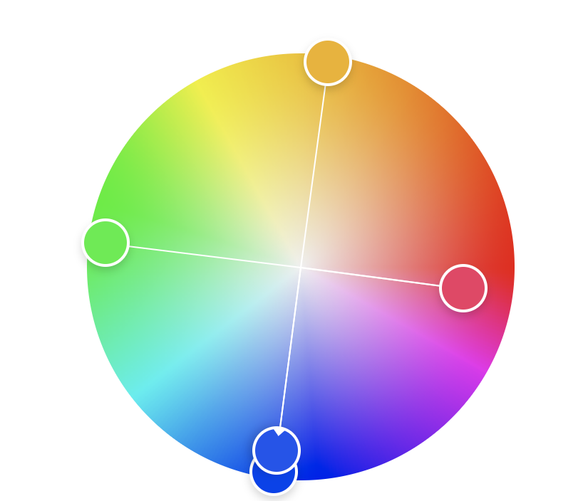
For consistency across the icons, I want to use the same white text for all labels. This requires tooling the color. Adjusting slightly for w3 contrast guidelines we are left with the following color scheme. This conceptually embodies the meaning behind quaternary logic, wile also creating maximum color contrast between logic states.
This color scheme drive the rest of the color use across the application, providing the primary base colors used for accent, warning, etc.
Shape
Through iteration of shapes. Joseph Potvin suggested the following shapes.
These shapes have an intuitive relationship with the logic state they represent.
Applied to the Icon shapes described by Joseph Potvin, the result is as follows. Particularly in the case of 10 and 11 the shapes convey that another step is needed, passing a piece of decision making along to human eyes.
All Together Now
Combining all of these decision the result is as follows:

And in the context of the layout the logic state icons have strong contrast, are readable at a glance, and do not fatigue the eyes.
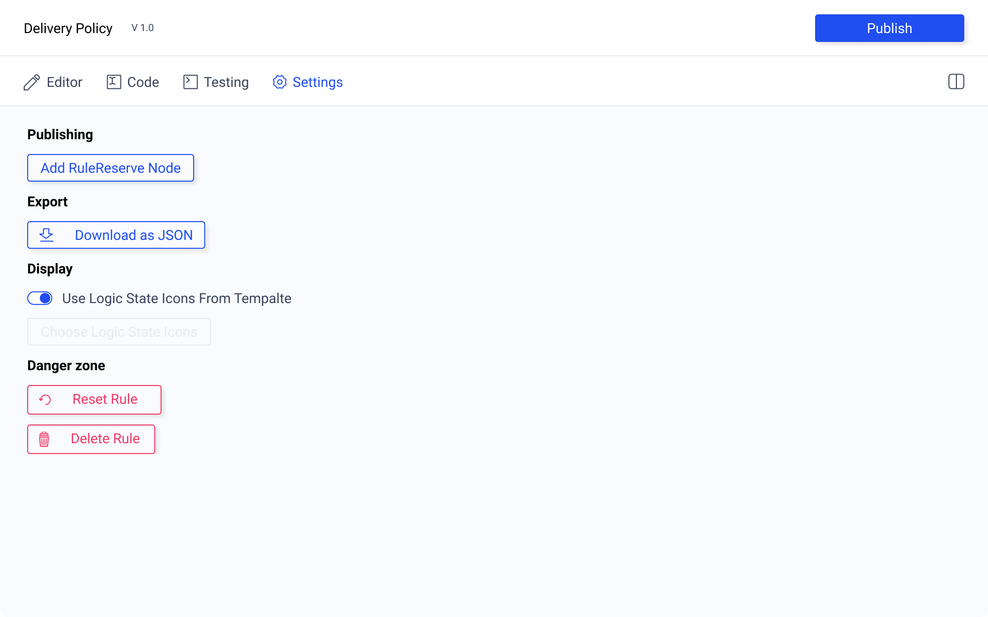
Custom Logic State Icons
Icons are a property of the rule template. They are useful because they may convey specific information that would be difficult to decipher without the correct iconogrpahic representation. For example, someone may be authoring rules within the tradition of formal logic. Without the corresponding logical symbols, the axiomatic statements may be incomprehensible.
![]()
In the settings tab there is an option to select if the author wants to use the custom icons contained within the rule template, or to select their own templates.
Ideas
have a paint bucket type method that allows you to select the logic icon that you want to use from a top menu
have multi click options
have hot keys that determine the logic state you'd like to input
drop down
doesn't work well, because the
This could be implemented in a control bar with column and row actions and the state selection tools all located there
The division between the sentences and the logic grid should allow for resizing.
the
| Context | User Need | Design Requirement |
|---|---|---|
| A user is authoring a rule using the table editor | User need to select and add logic states to the table. They must be able to select their tasks quickly and easily, as well as correct mistakes | Input condition, output assertion and row controls, including adding rows/columns, removing rows/columns and reordering. |
| Selection of logic states within the table | ||
| Ability to describe coordinates of logic state using row and column labels |
Introduction
The purpose of this document is to think though the ways in which an author would test their rule. This started out as a question of interface. However, I quickly realized that the problem I was trying to answer required understanding the relationship of the structured natural language sentence to both the is.xalgo message, and the UI methods used for testing.
The kind of testing I am investigating here has to do with table logic. I want a user to be able to check:
- if there are permutations missing from their truth table.
- if all the fields in a column are filled out in a desired manner.
- that given a scenario, the intended ought.xa message is returned.
I am not interested in testing:
- the structure of the json
- if the rule will be surfaced in a specific query
Scenario
| Input Conditions | A | B | C |
|---|---|---|---|
| The used capacity of the box is >= 0.5 | F | T | T |
| The measured type of the box == standard | B | B | T |
| The contained value of the box is >= $100.00 | B | F | T |
| Output Assertions | |||
| The described status of the delivery service is == offered | F | T | T |
| The advertized price of the delivery service is > $0.00 | F | T | F |
A user is writing a rule for a store policy on discounted shipping. They have completed the structured natural language sentences and the truth table. Now they want to check over the rule to make sure that everything is working. What options do they have?
UI Options
| Context | User need | UI Options |
|---|---|---|
| A user has authored a rule and must craft a sample is.xalgo message to send to rule reserve | A user wants to test the accuracy of their rule | An unpopulated text editor |
| a generated blob of JSON containing the field names required to generate a valid is.xalgo message | ||
| a simple form generated from the above JSON | ||
| a method to select the column the user wishes to test |
Unpopulated Text Editor
The user could craft a sample is.xalgo message using a text editor. However, this would require them to know the correct structure, would be time consuming, and present a barrier to those unfamiliar with the notation.
Generated JSON
This would do a better job of testing the logic that user is interested in assessing. However, the question arises. What does that JSON look like and how is the JSON generated for testing purposes?
Using column "A" from the example rule to generate an is.xalgo message, the JSON would contain something that looks like this:
"box": [
    {"capacity": "0.2"},
    {"type": "standard"},
    {"value": "100%"}
 ]
Great. Now we have the piece of JSON that is needed to accomplish the kind of testing the user is interested in. Knowing this structure, it is possible to generalize a method for generating a JSON structure that can be used for testing valid rule permutations.
The question now becomes, how is this piece of JSON derived from the user authored rule? Let's start by comparing the structured natural language sentence to the JSON using color to distinguish parts of speech as Joseph Potvin has done in the introductory Oughtomation paper.
sentence: The measured type of box == standard
JSON:
"box": [{"type": "standard"}]
This means that the structured natural language sentences authored by the user can be used to derive JSON for testing in the following way:
| Field within structured natural language sentence | Role in JSON data structure |
|---|---|
| subjectNoun | object |
| objectNounOrVerb | field |
| objectDescriptor | string |
I would like some feedback on this. Are my assumptions correct? Let's open this for discussion.
The user would be able to accomplish the desired testing if presented with the following in a text editor, filling in the fields to create a specific scenario:
"box": [
    {"capacity": ""},
    {"type": ""},
    {"value": ""}
 ]
If this thinking is correct, rule testing can easily be undertaken by a user using an interface that derives a JSON data structure from the rule authoring work already done.
Form Derived from JSON
If there is an accurate way to generate a valid JSON structure then there is no reason a form could not also be used to accomplish testing. This may be beneficial for users with little technical knowledge. There may also be advantages in application performance. It is probably less computationally demanding to fill out a small form, than to display and edit a potentially large is.xalgo message.
From the above JSON it is a small step to arrive at an html form. The only missing piece of data is a human readable label for each field. This could be as simple as using the field name as the label. However, as with the UI used for authoring rules, this can be confusing. A possible solution is to use the natural language sentence restructured as a question. In the English language example this is easily accomplished.
sentence: The measured type of box == standard
label formulated as question: The measured type of box is?
I'm not sure if this is feasible in other languages, but is worth investigating alongside the ongoing inquiry into the universality of the structured natural language sentence.
Column Select
Every valid test should correspond to a column in the truth table. In theory, testing could be accomplished by running columns. However, only allowing this will make it difficult to spot if there are unaccounted for scenarios. For this reason, it is important to have a method of authoring original is.xalgo messages.
That said, there should probably be a way to select a column and use it to populate an is.xalgo test message. Similarly, it would be useful to highlight on the table editor which column corresponds to the test is.xalgo message.
Conclusion
If asked to implement testing today, I would be inclined to include elements from the last three UI options. Being able to test using a form allows for users to quickly ensure they have authored a rule as intended. However, I also think there is value in being able to see the JSON structure of an is.xalgo message, even if that is not what is being tested. For this reason, I would likely have two tabs allowing the is.xalgo message to be edited using both methods. Finally, I would incorporate the functionality described in column select.